


 aa
aa
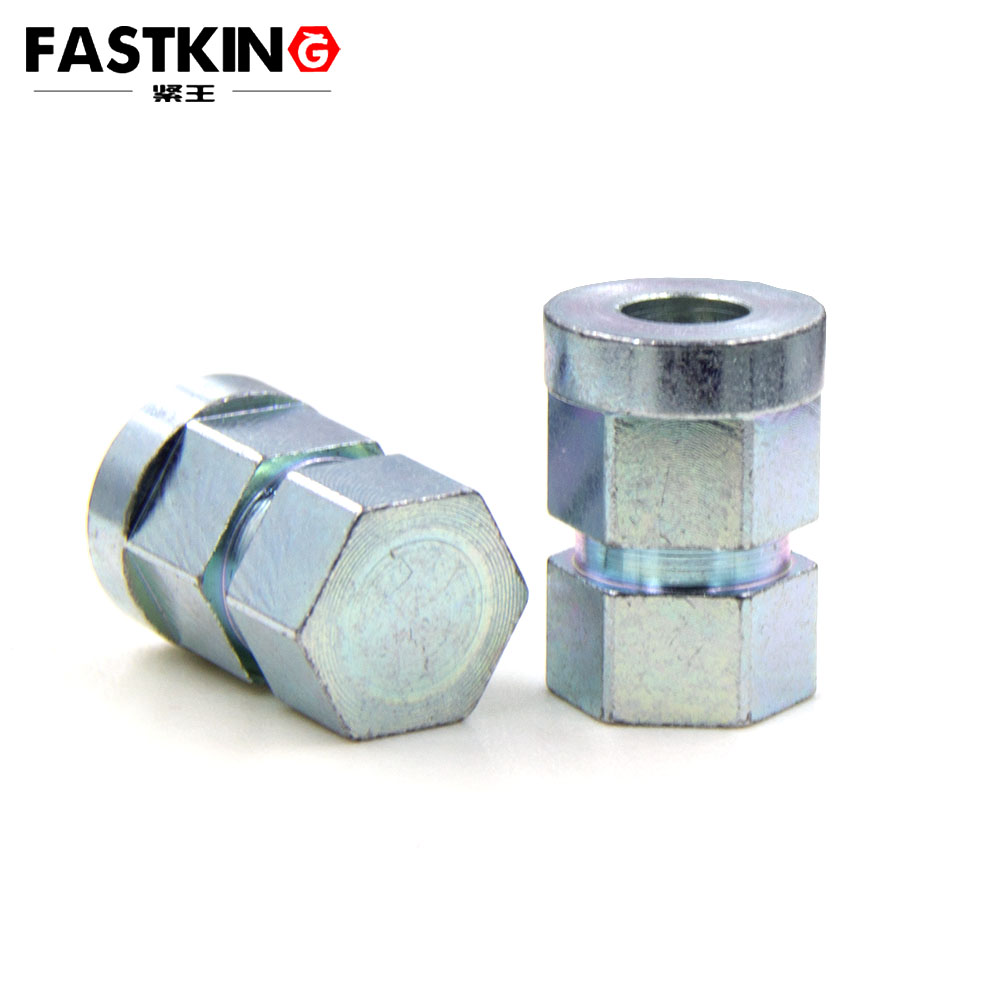
Basic Principles of Lathe Processing for Hexagon Nuts
Lathe processing is a type of cutting processing method that uses a lathe to make the workpiece rotate at a high speed, while the cutting tool moves linearly or in a curved path to remove excess material from the workpiece, thereby obtaining the required shape, size and surface quality. When applied to hexagon nut processing, the lathe mainly completes the machining of the nut's cylindrical blank, inner hole, thread and end face, laying a solid foundation for the subsequent processing of the hexagonal outer contour (usually completed by milling machines or stamping equipment).
The core principle of lathe processing for hexagon nuts lies in the coordinated movement of the workpiece's rotational motion and the cutting tool's feed motion. The workpiece (nut blank) is clamped on the lathe's spindle chuck, and as the spindle rotates, it drives the workpiece to rotate at a specific speed (cutting speed). Meanwhile, the cutting tool (such as turning tools, boring tools, threading tools) installed on the tool post moves in the axial (along the workpiece's central axis) or radial (perpendicular to the workpiece's central axis) direction according to the preset processing requirements. During this process, the cutting edge of the tool continuously cuts the surface of the rotating workpiece, removing metal chips and gradually forming the required geometric features of the nut.
For hexagon nuts, the key processing contents completed by lathe include: machining the outer circle of the blank to ensure the diameter meets the subsequent hexagonal processing requirements; boring the inner hole to form the basic hole for thread processing; turning the two end faces to ensure the thickness of the nut is accurate and the end faces are flat and perpendicular to the central axis; and cutting internal threads (using threading tools or tapping tools on the lathe) to enable the nut to match with bolts. These processing steps rely on the high-precision rotation of the lathe spindle and the accurate feed control of the tool, which are the prerequisites for ensuring the dimensional accuracy and geometric tolerance of the nut.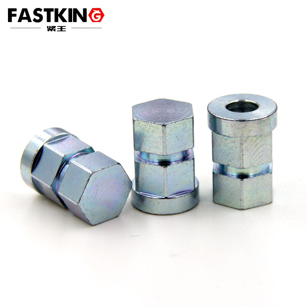
Detailed Processing Procedures of Lathe Processing for Hexagon Nuts
The lathe processing of hexagon nuts is a systematic process that requires strict adherence to the sequence of procedures to ensure processing efficiency and quality. The specific procedures are usually divided into the following steps:
1. Preparation Before Processing
Before starting lathe processing, comprehensive preparation work must be done to avoid errors during the processing process. Firstly, select the appropriate raw materials. The common materials for hexagon nuts include carbon steel (such as Q235, 45# steel), stainless steel (such as 304, 316), alloy steel and non-ferrous metals (such as copper, aluminum). The selection of materials should be based on the application environment of the nut (such as corrosion resistance requirements, load-bearing capacity requirements) and the customer's technical specifications. The raw materials are usually in the form of cylindrical bars, and the diameter of the bar should be slightly larger than the maximum outer diameter of the nut blank to reserve sufficient machining allowance.
Secondly, inspect and install the lathe and tools. Check whether the lathe's spindle rotation, tool post movement and cooling system are in normal working condition. Select the appropriate cutting tools according to the processing content: use a rough turning tool and a finish turning tool for outer circle and end face processing; use a boring tool for inner hole processing; and use an internal threading tool or a tap (for small-diameter threads) for thread processing. Install the tools on the tool post accurately, and adjust the tool's position and angle to ensure the cutting edge is aligned with the workpiece's center height (the deviation of center height will cause poor cutting quality, such as uneven cutting force and excessive tool wear).
Thirdly, clamp the workpiece. Cut the cylindrical bar into sections of a certain length (slightly longer than the thickness of the nut) using a sawing machine or a lathe's cutting tool to form the nut blank. Install the blank on the lathe's three-jaw chuck or four-jaw chuck: the three-jaw chuck is suitable for cylindrical blanks with uniform outer diameters and can realize automatic centering, which is efficient and convenient; the four-jaw chuck is suitable for blanks with irregular shapes or when higher centering accuracy is required, and each jaw can be adjusted independently to ensure the workpiece's coaxiality. After clamping, use a dial indicator to detect the runout of the workpiece's end face and outer circle, and adjust the chuck until the runout error is within the allowable range (usually ≤0.02mm), so as to avoid eccentric processing caused by inaccurate clamping.
2. Rough Processing
Rough processing is the first step of lathe processing, whose main purpose is to remove most of the excess material from the nut blank quickly, approaching the basic shape and size of the nut, while leaving a certain machining allowance for finish processing. The specific operations include:
Turning the End Face: Start the lathe, make the workpiece rotate at a low to medium speed, and move the rough turning tool to the end face of the workpiece. Feed the tool radially to cut the end face, removing the uneven part of the blank's end face (such as burrs, uneven cutting marks left by sawing) and ensuring the end face is flat. This step can also determine the length of the workpiece, so it is necessary to control the feed amount and cutting depth to avoid over-cutting.
Rough Turning the Outer Circle: After turning the end face, adjust the tool to the outer circle of the workpiece. Set the appropriate cutting parameters (cutting speed: 80-120m/min for carbon steel; feed amount: 0.2-0.5mm/r; cutting depth: 1-3mm), and move the tool axially to cut the outer circle of the blank. The diameter after rough turning should be 0.5-1mm larger than the finish size to reserve allowance for finish turning, which can reduce the cutting force during finish processing and improve the surface quality of the workpiece.
Rough Boring the Inner Hole: If the nut blank is a solid bar (not a pre-drilled pipe), it is necessary to first drill a pilot hole on the end face of the workpiece using a drill bit installed on the lathe's tailstock. The diameter of the pilot hole should be slightly smaller than the diameter of the nut's inner hole. Then, replace the drill bit with a boring tool, and perform rough boring on the pilot hole. The cutting parameters for rough boring are similar to those for rough turning the outer circle, and the inner hole diameter after rough boring should be 0.3-0.8mm larger than the finish size to ensure that the finish boring can correct the shape error of the inner hole.
3. Finish Processing
Finish processing is the key step to ensure the dimensional accuracy, geometric tolerance and surface quality of the hexagon nut. On the basis of rough processing, finish processing removes the reserved machining allowance with small cutting parameters, making the shape, size and surface of the nut meet the design requirements. The specific operations are as follows:
Finish Turning the End Face: Use a finish turning tool with a sharp cutting edge (the tool tip radius is usually 0.2-0.5mm) to process the end face of the workpiece again. The cutting speed for finish turning is higher (120-180m/min for carbon steel), the feed amount is smaller (0.05-0.15mm/r), and the cutting depth is 0.1-0.3mm. This step can make the end face's flatness error ≤0.01mm and the surface roughness Ra ≤1.6μm, ensuring that the thickness of the nut is accurate and the end face is perpendicular to the central axis (perpendicularity error ≤0.02mm).
Finish Turning the Outer Circle: Adjust the finish turning tool to the outer circle of the workpiece, and set the finish cutting parameters (cutting speed: 150-200m/min; feed amount: 0.1-0.2mm/r; cutting depth: 0.2-0.5mm). Move the tool axially to cut the outer circle, and control the final diameter of the outer circle to be consistent with the design size (tolerance range usually ±0.02mm). The surface roughness of the outer circle after finish turning should reach Ra ≤3.2μm, which provides a smooth surface for the subsequent hexagonal outer contour processing.
Finish Boring the Inner Hole: Use a finish boring tool to process the inner hole after rough boring. The finish boring tool has high precision (the tool tip runout ≤0.005mm), and the cutting parameters are set to high speed (100-150m/min) and small feed amount (0.05-0.1mm/r), with a cutting depth of 0.1-0.3mm. After finish boring, the inner hole's diameter tolerance should be controlled within H7 (for example, if the inner hole diameter is M10, the tolerance range is 10+0.015/-0mm), the roundness error ≤0.008mm, and the surface roughness Ra ≤1.6μm. These indicators are crucial for ensuring the smooth progress of subsequent thread processing and the tight fit between the nut and the bolt.
Internal Thread Processing: Internal thread processing is the core step of hexagon nut processing, and the common methods on the lathe include thread turning with a threading tool and tapping with a tap. For large-diameter threads (usually ≥M12) or threads with high precision requirements, thread turning is preferred: install the internal threading tool on the tool post, adjust the tool's angle to match the thread's helix angle (for metric threads, the standard angle is 60°), set the lathe's spindle speed (calculated based on the thread pitch, usually 30-80r/min) and feed amount (equal to the thread pitch), and then perform multi-pass cutting (the number of passes depends on the thread depth, usually 3-5 passes) until the thread's depth and profile meet the requirements. For small-diameter threads (usually ≤M10), tapping is more efficient: install the tap on the lathe's tailstock, align the tap with the inner hole of the workpiece, and drive the tap to rotate and feed axially through the tailstock's handwheel or power device to form the internal thread. After thread processing, it is necessary to check the thread's pitch, major diameter, minor diameter and profile using a thread gauge (such as a plug gauge) to ensure that the thread can be smoothly matched with the corresponding bolt (the fit tolerance is usually 6H for nuts).
4. Post-Processing and Inspection
After completing the lathe processing, the hexagon nut needs to undergo post-processing and strict inspection to ensure its quality meets the standards. Post-processing mainly includes de-burring and surface treatment: de-burring is to remove the burrs and sharp edges generated during cutting (such as the burrs at the end of the thread, the edge of the end face) using a file, sandpaper or a de-burring machine, which can prevent the nut from scratching the operator's hands or other components during installation; surface treatment methods include galvanizing (hot-dip galvanizing, electro-galvanizing), chrome plating, nickel plating, phosphating, etc., which can improve the nut's corrosion resistance, wear resistance and aesthetic appearance. For example, galvanized nuts are suitable for indoor dry environments, while stainless steel nuts with passivation treatment are suitable for outdoor or corrosive environments (such as marine engineering).
Quality inspection is an important link to ensure the reliability of the hexagon nut. The inspection items mainly include:
Dimensional Inspection: Use a caliper (digital caliper, vernier caliper) to measure the outer diameter, inner hole diameter, thickness and thread pitch of the nut; use a micrometer to measure the outer diameter and inner hole diameter with high precision (measurement accuracy up to 0.001mm).
Geometric Tolerance Inspection: Use a dial indicator to detect the flatness of the end face and the coaxiality of the inner hole and outer circle; use a straightedge and feeler gauge to check the perpendicularity of the end face and the central axis.
Thread Quality Inspection: Use a thread plug gauge to check the fit of the thread (the go gauge should pass through smoothly, and the no-go gauge should not pass through); use a thread profile projector to observe the thread's profile shape and check whether there are defects such as incomplete threads or tool marks.
Mechanical Property Inspection: For nuts used in important occasions (such as automotive engines, aerospace equipment), it is necessary to conduct mechanical property tests, such as hardness test (using a Brinell hardness tester or Rockwell hardness tester to check the surface hardness of the nut, which should meet the requirements of the material standard, such as 45# steel nuts with a hardness of HB180-220), tensile test (testing the nut's tensile strength and yield strength) and torque test (testing the maximum torque that the nut can bear without damage when matched with the bolt).
Key Technical Points and Common Problems in Lathe Processing of Hexagon Nuts
To improve the processing quality and efficiency of hexagon nuts, it is necessary to master the key technical points of lathe processing and solve common problems in a timely manner.
Key Technical Points
Selection of Cutting Parameters: The selection of cutting speed, feed amount and cutting depth directly affects the processing efficiency, tool life and workpiece quality. For different materials, the cutting parameters should be adjusted accordingly: for high-hardness materials (such as alloy steel), lower cutting speed and smaller feed amount should be used to reduce tool wear; for soft materials (such as aluminum), higher cutting speed and larger feed amount can be used to improve processing efficiency. At the same time, during finish processing, small feed amount and high cutting speed should be used to ensure the surface quality of the workpiece.
Tool Installation and Adjustment: The accuracy of tool installation is crucial for ensuring the processing accuracy of the nut. When installing the tool, it is necessary to ensure that the tool's center height is consistent with the workpiece's center height (the deviation should be ≤0.01mm), otherwise, the cutting edge will not cut the workpiece evenly, resulting in errors in the outer circle or inner hole diameter. In addition, the tool's clamping should be firm to avoid tool vibration caused by loose clamping, which will affect the surface roughness of the workpiece.
Cooling and Lubrication: During lathe processing, a large amount of heat is generated due to the friction between the cutting tool and the workpiece, which will not only accelerate tool wear but also cause thermal deformation of the workpiece, affecting the processing accuracy. Therefore, it is necessary to use a suitable cutting fluid for cooling and lubrication. For carbon steel and alloy steel processing, emulsion (water-based cutting fluid) is usually used, which has good cooling effect; for stainless steel and non-ferrous metal processing, cutting oil (oil-based cutting fluid) is used, which has good lubrication effect and can prevent the workpiece from sticking to the tool. The cutting fluid should be sprayed evenly on the cutting area to ensure that the tool and workpiece are fully cooled and lubricated.
Control of Machining Allowance: The machining allowance reserved for rough processing and finish processing should be reasonable. If the allowance is too large, it will increase the number of cutting passes, reduce processing efficiency and increase tool wear; if the allowance is too small, it will not be able to correct the shape error and surface defects caused by rough processing, resulting in unqualified finish processing quality. Generally, the rough machining allowance for the outer circle and inner hole of the nut is 0.5-1mm, and the finish machining allowance is 0.1-0.3mm.
Common Problems and Solutions
Eccentricity of Outer Circle or Inner Hole: The main reasons for this problem are inaccurate clamping of the workpiece (such as the workpiece is not centered in the chuck) or excessive runout of the lathe spindle. The solution is to re-clamp the workpiece, use a dial indicator to adjust the chuck until the runout error of the workpiece is within the allowable range; if the spindle runout is excessive, it is necessary to maintain or replace the lathe spindle bearings.
Poor Surface Quality of Workpiece (such as rough surface, tool marks): This is usually caused by dull tool edges, inappropriate cutting parameters (such as too large feed amount, too low cutting speed) or insufficient cooling and lubrication. The solution is to replace the tool with a new one or re-grind the cutting edge; adjust the cutting parameters to increase the cutting speed and reduce the feed amount; check the cutting fluid supply system to ensure that the cutting fluid is sprayed normally.
Incorrect Thread Pitch or Profile: The main reasons are incorrect setting of the lathe's feed box (the feed amount does not match the thread pitch) or incorrect angle of the threading tool. The solution is to re-calculate the feed amount according to the thread pitch and adjust the feed box of the lathe; re-adjust the angle of the threading tool to ensure that it is consistent with the thread's helix angle (use a thread gauge to check the angle).
Cracking of Workpiece During Processing: This problem is usually caused by using materials with poor quality (such as materials with internal defects, such as inclusions, cracks) or excessive cutting force (such as too large cutting depth, too small cutting speed). The solution is to inspect the raw materials before processing, and select materials with qualified quality; reduce the cutting depth and increase the cutting speed to reduce the cutting force.